Warning: The following instructions must be read and understood before installing and maintaining the product. Failure to follow these instructions may result in danger!
Safety: Safety instructions must be observed. Leave this manual for the user. Dispose of the product in compliance with current legislation.
Function: Fernox TF1 Antifreeze Valves allow drainage of the medium when the circuit temperature reaches an average value of 3 °C.
Warranty: Fernox covers the product for a warranty period of 5 years as long as it is used in the correct manner and under the terms indicated in the technical specifications listed.
Installation, commissioning, and maintenance instructions
Preparation for installation: Ensure that the pipes are clean. Do not allow debris, tape, or any other solid element to settle in the system.
Technical Data
| Maximum static operating pressure | 10 bar |
| Operating temperature range | 0-75 °C |
| Ambient temperature range | -30/60 °C |
| Fluid temperature (opening) | 3 °C |
| Fluid temperature (closed) | 4 °C |
| Accuracy | ±1 °C |
| Fluids | Water |
| Materials | Brass alloy CW 617 N-DW |
| Thread | ISO228 |
Installation
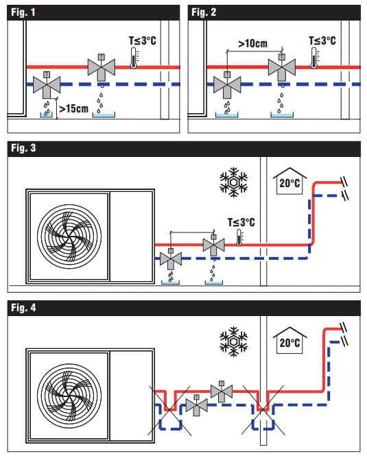
Fernox TF1 Antifreeze Valves must only be installed in a horizontal position, with the outlet facing downwards, to allow the drained water to flow out properly and free from obstructions.
Fernox TF1 Antifreeze Valves must be installed externally, in the coldest part of the system, where there is a risk of frost. It is recommended to install a Fernox TF1 Antifreeze Valve on both pipes (flow and return Fig. 3). They must also be positioned away from heat sources that could affect correct operation.
Keep a distance of at least 15 cm from the ground in order to prevent the formation of an ice column in the area preventing water from escaping from the valve (Fig. 1). Maintain a distance of at least 10 cm between the antifreeze valves so that, in the event of a discharge, the valve positioned above does not discharge onto the valve below (Fig. 2). In-line with regulations, the discharge from the antifreeze valve must be routed into an appropriate collection tray or pipe. It is advisable to keep the system under pressure at all times, even when draining a Fernox TF1 Antifreeze Valve.
In very hard water areas there must be provision for adequate filtration and water treatment of the water before it enters the system, according to technical standards.
Do not make any trap connections.
If the shape of the connection pipe has the potential to create a trap effect (as shown in Fig. 4), drainage is prevented and frost protection will no longer be guaranteed
Insulation
To ensure the system is working at optimum efficiency, only the body valve must be insulated and the thermostatic sensor uncovered. When installed externally, the valve must be protected from rain, snow, and direct sunlight.
Maintenance
CAUTION: Before carrying out maintenance, ensure that the system is turned off or under pressure.
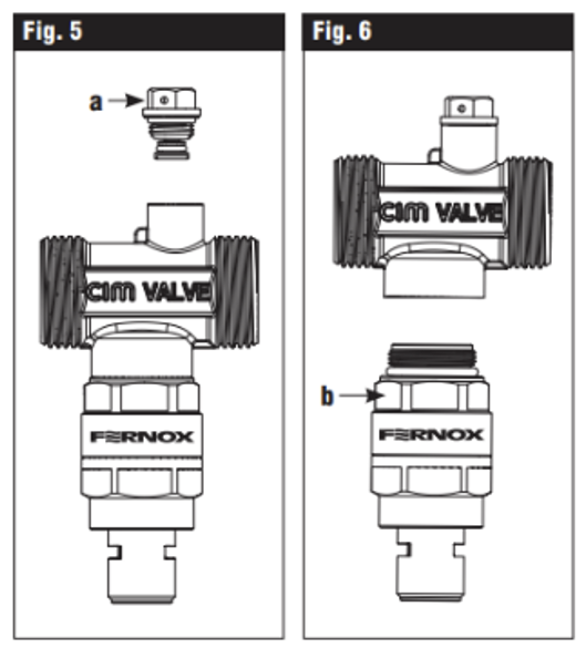
Replacing the vacuum breaker (Fig. 5) Unscrew the vacuum breaker (a) with a fixed hexagonal spanner and pull it out of the valve body. Replace it with the spare part.
Replacing the thermostatic cartridge (Fig. 6) Unscrew the cartridge to replace the thermostatic device (b) with its replacement part.